Building Bridges
Modular Bridge
Here for your consideration is a modular bridge system intended for model railways, wargaming, slot car circuits and other dioramas.
These can be produced in any of the major model railway, slot car and wargaming gauges/scales.
Whilst the samples illustrated are intended to suit Peco N gauge sectional track they are only a fraction of what can be supplied, the sections can be produced in any of the major model railway, wargaming and slot-car scales with differing spans, roadbed widths and roadbed and arch heights.
I believe the major features are as follows
* Can be sized to suit from Z through N, TT, OO/Ho, S, O to gauge 1 and above
* Your choice of arch heights and spans, and also road bed widths (multi track capability).
* Curved viaducts a speciality, your choice of angle per arch (to match your flex-track design)
* Really quick and easy to put together, the bridge can be assembled in minutes
* Once assembled it can be moved as one item
* Just as easy to disassemble, the sections can be reused as required
* Strong, the single track 87mm N gauge section arch supports over 50kg#.
* Does not rely on ageing glued joints. Not affected by damp, no veneers to delaminate or MDF to rot
* Does not need to be painted, "scribed" brick~mortar version in earth red or a smoother plain finish in grey, but naturally you may repaint, weather and detail these as you desire.
* Choice of pillar designs, can be adapted as buttresses for your own girder designs.
* Sections can be custom made to suit your exact requirements, height, span, roadbed width, balustrade height, slots for slot car guides or contact strips, slots for "Faller" style magnetic guides.
If you have the need then varying width roadbeds could be arranged (to suit points/turnouts or road junctions) or for an inclined roadbed (spiral viaducts?).
If you wish to use this system as an approach span for plate or open girder bridges then a custom pier can be produced to suit abutments for those.
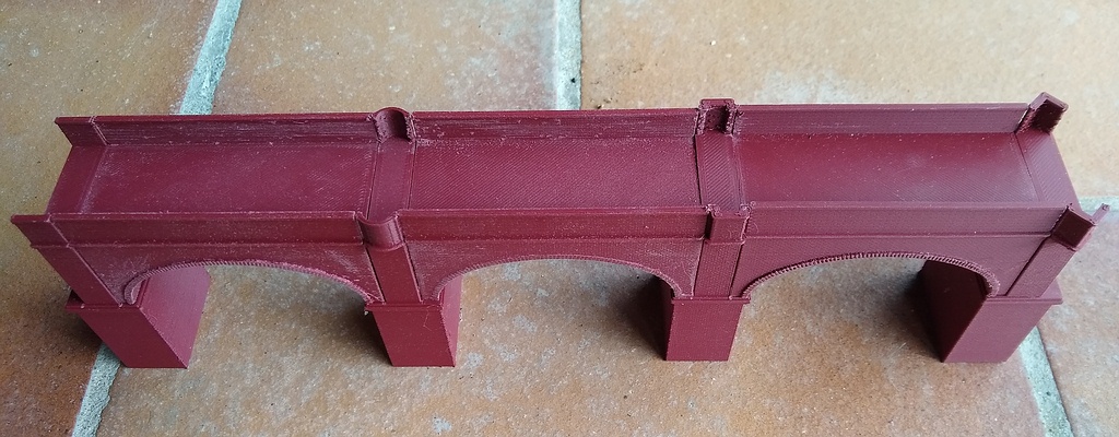
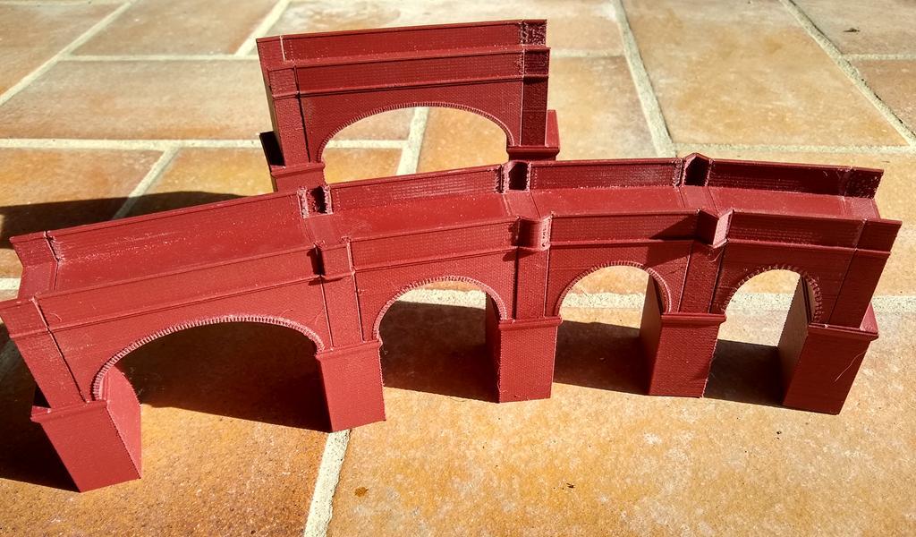
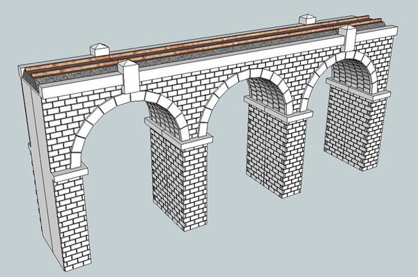
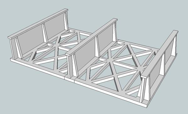
illustrating a simple 3 arch viaduct for 87mm straights. L to R plain curved, rectangular and triangular pier balustrades.
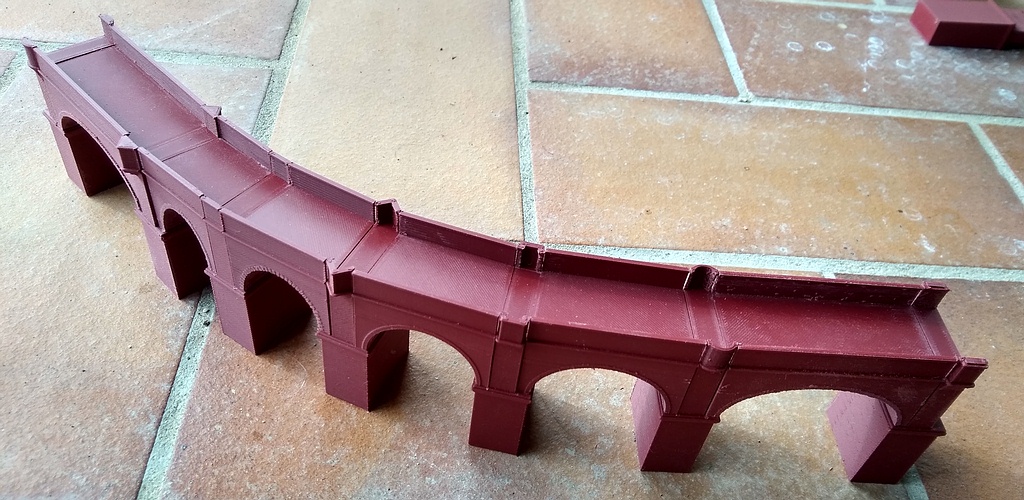
curved viaduct with 87mm straight section followed by R1, R2, R3 and R4 angled sections plus a further 87mm straight section
The "solid" curved and triangular pier balustrades can be seen to the left, that for the regtangular design to the right.
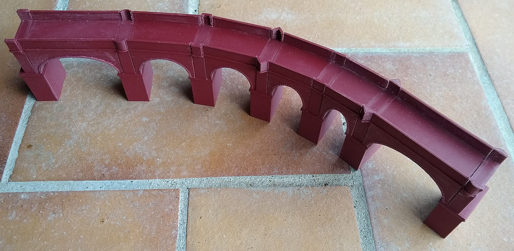
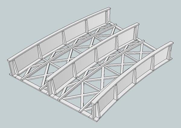
and from the other, inner curve side and also from above
Illustrating (L to R) the "plain", "rectangular", "curved", "angled" and another "plain" wall for the pillars
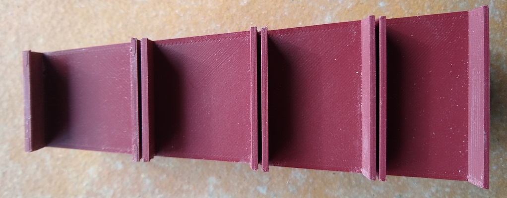
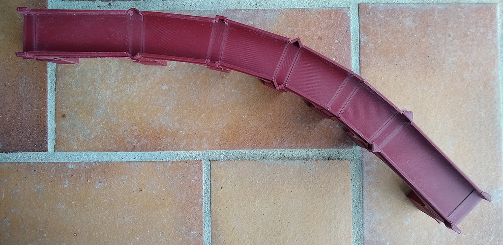
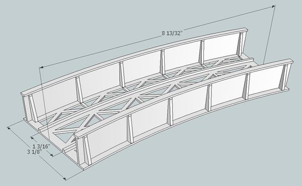
Illustrating the sections intended for 1st, 2nd, 3rd and
4th radius Peco N gauge settrack. You may readily imagine how these
designs can be merged (retaining the outermost balustrades) to give
twin, triple or wider roadbeds. The system is intended to fit your track
design rather than force you to plan around a limited choice of
commercial products.
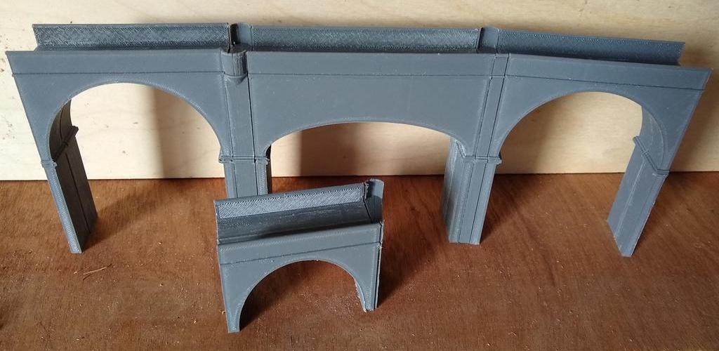
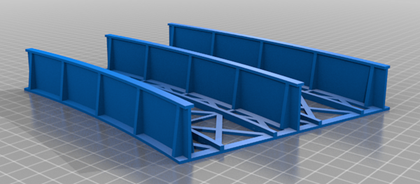
Illustrating some options for arch widths and heights and also the grey smooth finish of a previous design style
PLEASE CHECK for CLEARANCE
You know the items that you want to traverse the bridge, I do not, please check that your most "difficult" items will clear.
For straight track this is pretty straight-forward, simply check for the widest item you expect to use and allow extra for any yaw or sideways displacement that this or other likely candidates display.
For curved track you need to take more care. The items most likely to interfere with the outer balustrade is a long locomotive, either rigid chassis or prototypically articulated mallet.
With the inner balustrade it might often be the longest bogie coach or freight item that you have or possibly the cylinders of a large locomotive.
My suggestion is that you lay down the track on a flat surface and replicate the sharpest curves that you intend to use on or approaching the bridge.
Having done that get two vertically sided objects that can act as moveable pillars (rectangular boxes or coffee mugs perhaps) and place them either side of the track.
Now gently run or push the likely most problematic items around the curve, moving the boxes/mugs away away from the track until all can pass clearly.
![]()
When that has been done carefully measure from the near edge of the mugs to the centre-line of the track.
The tightest point on the outer (OT) would be expected to be at mid-span and for the inner (IT) at the piers.
A very close approximation for the total width needed between balustrades (with no gap allowance) is given by
OT+IT+NominalRadius(1-cos(0.5*AngleOfSector))
to which should be allowed an air gap either side which would depend on how much combined lateral slop there is in the wheels on the track, the axles in the bearings etcetera.
The Morop/NEM recommended minimum for inter-track spacing for N gauge straight track is 25mm. For curved track they recommend increasing this by 10 mm at 300mm radius petering out to 4mm at 550mm radius. Peco settrack curves use a spacing of 35mm.
If you want to run very large locomotives or any particularly long or wide stock around tight curves then the balustrades can be lowered or removed.
Custom Items
It is my opinion that a bridge should fit in with your track plan rather than the other way around.
If you would like a bespoke item then please get in touch for the modular bridge "specification sheet" which details the dimensions, minima and maxima, that can be chosen.
# The balustrades are not expected to support such a load, for this test a piece of 100mmx25x25mm softwood was placed along the roadbed and 72 Kg loaded on to the wood. This was not a point load at mid span and I am not saying that this was a perfectly evenly distributed load but in comparison with other forms of model bridge it seemed strong enough. It did not fail at 72Kg, I got bored with locating extra weights. I have backed the claim down to 50Kg to give a margin to cover any variation in supplied materials and ageing, it is not likely to collapse and damage your favourite locomotive or train.
I would not recommend parking a lit live steam locomotive on these products for any length of time but neither would I risk that on a ply or MDF structure.
_______________________________________________________________________________________________________
Other Bridge styles
Please get in touch if you fancy anything from the following designs
Remagen
If you like the idea of a baby "Remagen" then I can also supply this.
Please note that the "Remagen" model is more in keeping with the film site. The actual bridge at Remagen was considerably longer.
If, as per the film, you would like to run a "Remagen" model for alternating functional road and rail traffic I can suggest methods of doing so.
Road Bridge
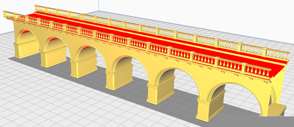
The "Road Bridge" is typical of many town/city river crossings. With the overhanging pedestrian pavements and fancy balustrades it does not suggest itself to mainline rail traffic. I can however easily imagine a light tramway crossing such a bridge. The design can be rescaled, sliced or stretched to a moderate extent to accomodate a range of spans. For N scale and below it is suggested to replace the balustrade pillars with a solid wall.
Trestle Bridge
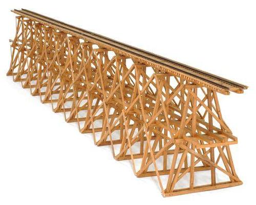
The old stand-by for prototypical speed of construction and often favoured where there was a ready supply of hardwood there is something that draws the eye to a nicely constructed testle bridge.
Normally, in model terms, constructed out of stripwood or adjusting the scenery to suit one of the few plastic kits this sectional design once again allows for variation in overall length and any reasonable height and curvature that you want.
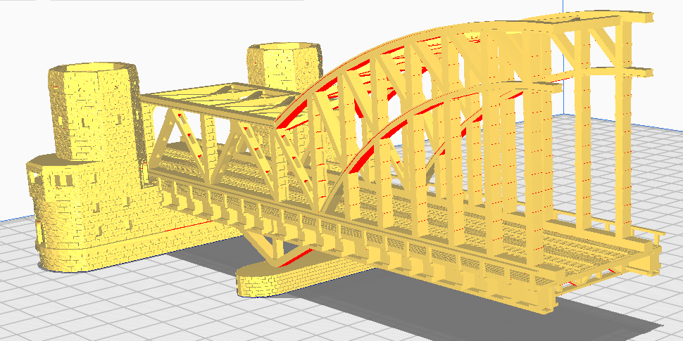
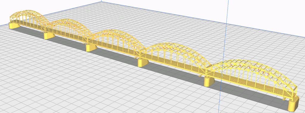
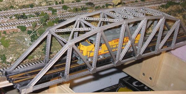
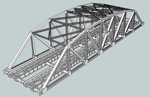
Steel Arch Bridge
Suitable for road or rail, easily extended should you
need to cross an estuary.
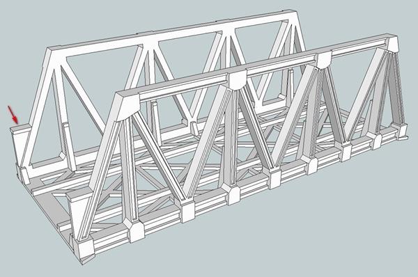
Simple short bridges, though the designs can be extended
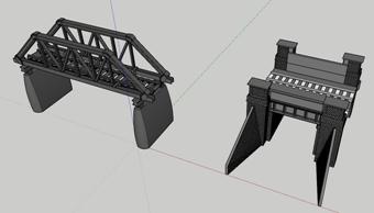
Small Plate Girder and Open Girder bridges
Here are a series of prepared designs. As well as overall enlargement to suit different scales the designs can be stretched by varying amounts regarding length, width and height as may better suit your particular needs. The aspect ratio of beams and of the brick pattern may alter from this but unless the stretch or compression is very uneven it may not be noticed by the casual observer. The original designs were for Ho and thus track beds suit OO also.
Masonry
126 ft Highway
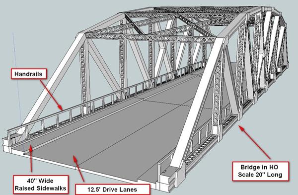
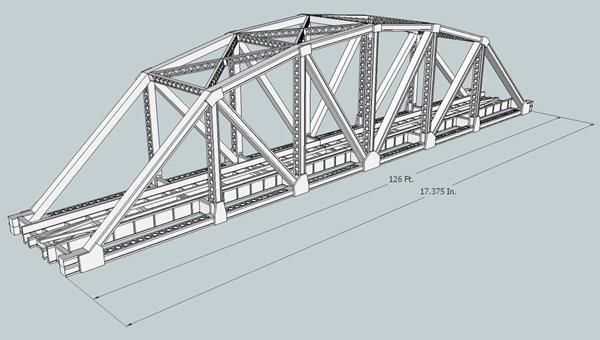
Single Track 126 ft
Single track 145 ft
Dual Track 145 ft
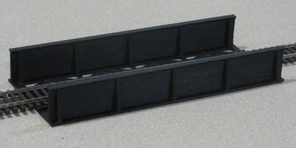
Timber Deck
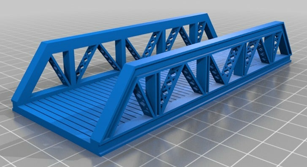
Plate Girder
In the case of plate girder bridges, these designs can also be stretched though the design is simple enough to permit an individual print to your choice of span, curvature, number of panels and lanes.
Some examples:

![]()
 monsieurvapeur home page